Part of my love letter to math.
Much of math revolves around modeling real-world problems. These models must capture sufficient complexity from the underlying problem, but still simplify enough to permit clean analysis. The art of mathematical modeling, then, is to find that perfect balance between complexity and elegance—and when done well, it fascinates me endlessly.
Flow
The model
How much water flow can you push through a pipe system? To answer this question with absolute fidelity, we must consider a plethora of physical constraints, e.g.:
- What are the pipes made of? (pipe material)
- How fast is the water moving? (water velocity)
- How are the pipes and junctions connected? (network structure)
…but the physical world is way too complicated, and we’re mathematicians! So to form a good model, we must decide which of these constraints are the most important, and which we should discard.
Although this selection process is certainly subjective and depends heavily on the intended use case, I think it’s reasonable to select network structure as the most important factor. After all, we can overcome the other two constraints—pipe material and water velocity—simply by constructing stronger pipes; but network structure contributes the bulk of the problem’s complexity, as bad structure can create subtle bottlenecks that can’t be solved by just simple pipe reinforcement.
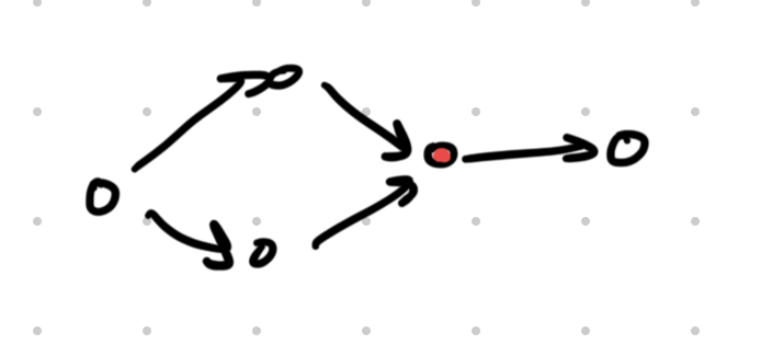
An example of bad network structure—the red junction always bottlenecks flow.
So for our model, let’s try reducing the pipe system to just to its network structure: how pipes and junctions are connected, as well as the capacities of each pipe.
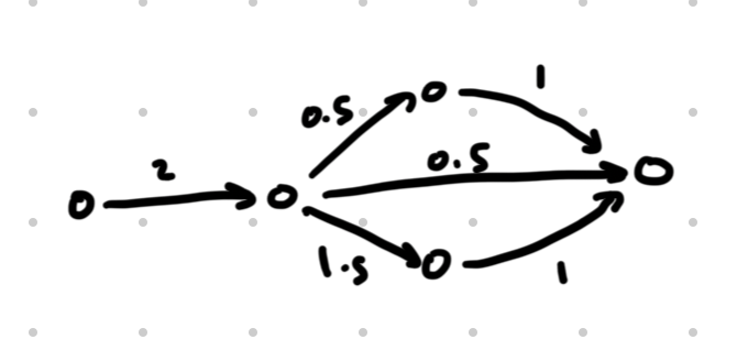
How we depict the network structure graphically—the circles (nodes) denote junctions, the arrows (edges) denote pipes, and the number above each pipe represents its capacity. When numbers are omitted, you may assume a capacity of 1.
The maximum flow in the network illustrated above is 2, which we can achieve like so:
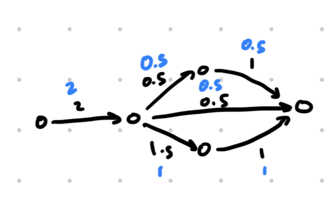
The blue numbers denote the amount of flow pushed through each pipe.
Observe that the flow must obey two constraints:
- Capacities. The amount of flow pushed through a pipe cannot exceed the capacity of that pipe.
- Conservation. For each junction, the amount of entering flow must equal the amount of exiting flow.
- For instance, the leftmost junction has 2 units of entering flow and units of exiting flow, so it satisfies conservation.
With these definitions and constraints, we’ve established all the motivation and rules for our model! Now, it’s time to play around with it and see what cool results we can derive.
The results
Min-cut max-flow theorem
You might suspect a relationship between the maximum flow and the smallest “bottleneck” in the system; and amazingly, we can actually transform this rough intuition into a precise mathematical equivalence. The min-cut max-flow theorem states the following:
In a pipe network, the maximum flow and minimum cut (bottleneck) are exactly equal.
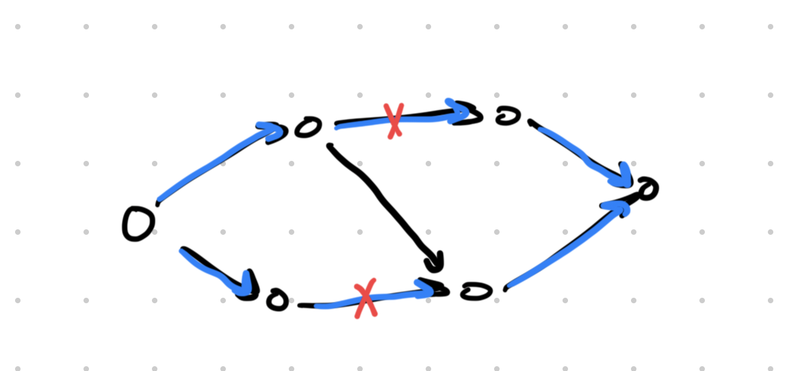
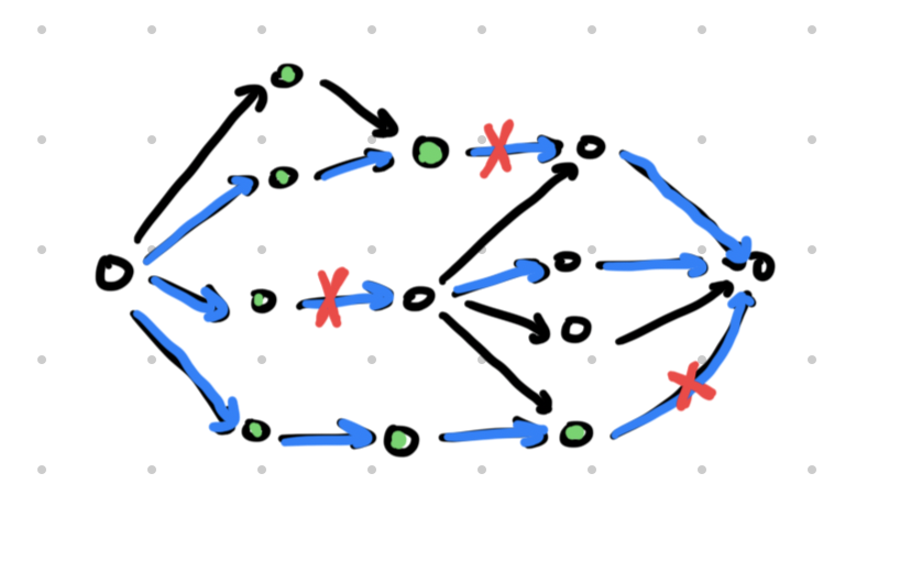
An example network that has a maximum flow of 2 (shown in blue) and a minimum cut of 2 (shown in red).
What counts as a cut?
A cut is a valid cut if, after we delete all the edges in that cut from the network, the sink is no longer reachable from the source. For instance, in the graph below, the three red edges form a valid cut because after deleting them, the source can no longer reach the sink. The green nodes are the nodes that can still be reached from the source.
Metric social choice
Under construction, see Voting for now.